
NDT for Defence Forgings in India: UT, MT, PT, and NABL Requirements
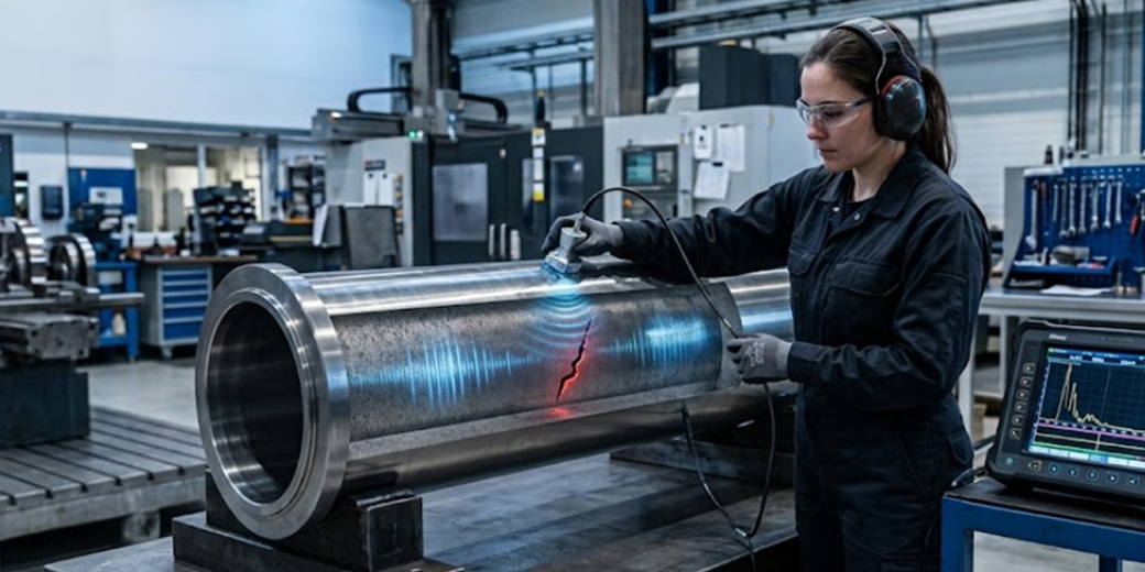
Non-destructive testing for defence forgings is the inspection regime applied to forged components after manufacturing to detect internal and surface defects without destroying the component. For defence applications in India, NDT is not an optional quality check applied at the discretion of the manufacturer — it is a mandatory requirement specified in the quality plan for every safety-critical forged component, performed by qualified operators using calibrated equipment, to acceptance criteria that are among the most stringent applied in any manufacturing sector.
Why NDT Is Non-Negotiable in Defence Forging
A forged component can be dimensionally correct, meet specified hardness, and carry the right heat number on its traveller — and still contain an internal defect that will cause structural failure under service loading. Hydrogen-induced cracks forming during cooling, non-metallic inclusion clusters inherited from the ingot, micro-porosity in a heavy-section forging that the forging process did not fully close — none of these are visible to any other inspection method. Without NDT they reach the field.
In defence applications the consequences of structural failure in service are not commercial. A propulsion shaft forging that fails on a destroyer under power, a torsion bar that fractures during off-road operation of an armoured vehicle, a missile motor case that fails under proof pressure — these are safety and mission critical events. NDT is the last manufacturing control between a process-derived defect and a structural failure in operation.
This is why no credible defence programme quality plan in India omits NDT from the forging supply chain. The question is not whether NDT is required — it is which methods, to which standards, performed by which operators, to which acceptance criteria.
At a Glance: NDT Methods for Defence Forgings
| Method | Detects | Material Applicability | Typical Standard | Who Performs |
| Ultrasonic Testing (UT) | Internal volumetric defects | All metals | ASTM A388, AMS 2154 | ASNT Level II |
| Magnetic Particle (MT) | Surface and near-surface | Ferromagnetic steels only | ASTM E709, ASME V Art.7 | ASNT Level II |
| Dye Penetrant (PT) | Surface-breaking defects | All non-porous materials | ASTM E165, ASME V Art.6 | ASNT Level II |
| Radiographic (RT) | Internal defects — 2D image | All metals | ASTM E94, ASME V Art.2 | ASNT Level II + RT specialist |
| Eddy Current (ET) | Surface and near-surface | Conductive materials | ASTM E309 | ASNT Level II |
| Phased Array UT (PAUT) | Internal — enhanced resolution | All metals | ASTM E2700 | ASNT Level II PAUT certified |
Ultrasonic Testing: The Primary Method for Defence Forgings
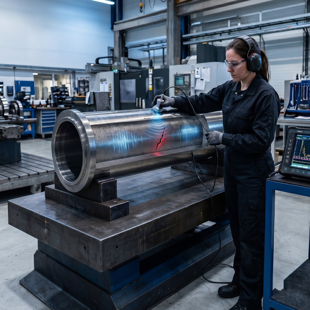
UT is the primary volumetric inspection method for all defence forgings. A transducer introduces high-frequency sound pulses into the forging. Internal discontinuities reflect sound back to the transducer — the time of flight and amplitude of reflected signals reveal the location and relative size of defects.
Scanning Coverage
For defence forgings, 100% volume coverage is required for safety-critical components. This means the sound beam must interrogate every cubic centimetre of the forging volume — not a sample, not a grid pattern with gaps. Achieving 100% coverage requires multiple scanning passes in multiple directions for complex geometry, using immersion UT, contact scanning with index points, or phased array techniques where geometry restricts conventional probe access.
Contact UT vs Immersion UT
Contact UT — the probe is placed directly on the forging surface with coupling gel. Fast to set up, flexible for field use, but sensitive to surface condition and operator technique. Suitable for large flat-faced or cylindrical forgings.
Immersion UT — the forging is submerged in a water tank and scanned by a probe that does not contact the surface. Higher sensitivity — the water path eliminates near-surface dead zones and coupling variability. Required by some programme quality plans for aerospace and missile grade forgings where acceptance criteria are tightest.
Phased Array UT (PAUT) — electronically steered beam provides multiple angle coverage without moving the probe. Particularly effective for complex geometry forgings — turbine disc profiles, housing forgings with internal bores, transition sections with varying wall thickness. Increasingly specified in new Indian defence programme quality plans.
Calibration and Reference Standards
Before each UT inspection session the instrument and probe are calibrated against a reference standard — a piece of the same material specification as the production forging, containing flat-bottom holes of defined diameters at defined depths. The calibration defines the sensitivity — the minimum flaw size that produces a rejectable indication.
The reference standard is a controlled quality tool. It must be made from the same material specification, heat treated to the same condition, and machined to the same surface finish as the production components. A reference standard that does not match the production material introduces systematic error into the UT calibration.
For defence programme UT, the calibration standard is documented in the written UT procedure. The procedure identifies the specific reference standard by serial number, the calibration method, the scanning pattern, and the acceptance criteria. This procedure is a controlled document reviewed during AS9100D and DGQA audits.
UT Acceptance Criteria for Defence Forgings
ASTM A388 is the most commonly referenced standard for carbon and alloy steel defence forgings in India. It defines the examination technique, calibration requirements, and acceptance criteria for several quality classes. The class specified in the procurement document determines the acceptance threshold.
For critical defence applications — missile structural steels, aircraft landing gear forgings, nuclear pressure-retaining components — customer-specific acceptance criteria typically exceed ASTM A388.
These may specify:
- Smaller maximum acceptable flat-bottom hole equivalent (FBH equivalent) — as low as 1/32 inch (0.8mm) for the most demanding
- Tighter back-wall attenuation limits — indicating material cleanliness below what A388 requires
- Restricted zones with tighter acceptance than the bulk of the forging
Acceptance criteria are specified in the quality plan for each programme and are not negotiable. A UT indication that exceeds the acceptance threshold is a rejection — disposition options are limited to scrap or engineering review with OEM approval.
Magnetic Particle Inspection: Surface and Near-Surface Detection
MT is the standard surface inspection method for all ferromagnetic steel defence forgings — all alloy steels, carbon steels, and armour steels. It detects surface and near-surface defects (typically to 3mm depth) by creating a magnetic flux in the component and applying iron particles — dry powder or wet fluorescent suspension — that concentrate at flux leakage points created by surface-breaking or near-surface defects.
When MT Is Performed
MT is most effective — and most appropriately performed — after final machining, when the component is in its final surface condition. Performing MT on an as-forged surface with scale and roughness reduces sensitivity. A crack or seam that opens fully after machining may not be detectable in the as-forged condition.
For components that receive grinding after heat treatment — torsion bars, gear blanks with precision surfaces — MT after grinding is mandatory. Grinding cracks are a known failure mode for high-hardness steels and are undetectable without MT at the finished surface.
Magnetisation Directions
A single magnetisation direction detects only defects oriented approximately perpendicular to the field direction. Defects parallel to the field are not detected. For defence forgings, at least two magnetisation directions perpendicular to each other are required to ensure all orientations of potential defects are covered. For complex geometry with multiple surfaces and directions, additional magnetisation passes may be required.
Wet Fluorescent MT
Wet fluorescent MT — using fluorescent iron particles in a petroleum or water carrier, inspected under UV (black) light — provides significantly higher sensitivity than dry powder MT under white light. For defence programme MT, wet fluorescent technique is increasingly specified because of its superior sensitivity to tight fatigue cracks and small seams. The UV lamp intensity and wavelength must be verified and documented before each inspection session.
MT Standards for Defence
ASTM E709 is the primary standard for MT technique. ASME Section V Article 7 is referenced for pressure-bearing components under the IBR or ASME Code scope. Customer-specific acceptance criteria reference the applicable standard and define what constitutes a rejectable indication — typically any linear indication above a defined length, or any rounded indication above a defined diameter in a restricted zone.
Dye Penetrant Testing: Surface Detection for Non-Ferromagnetic Materials
PT is used for titanium, aluminium, austenitic stainless steel, and Inconel forgings where the ferromagnetic requirement for MT cannot be met. The principle is simple — a liquid penetrant is applied to the clean surface, allowed to dwell in surface-breaking defects by capillary action, excess is removed, and a developer draws the entrapped penetrant back to the surface to create a visible or fluorescent indication.
Fluorescent Penetrant Inspection (FPI)
Fluorescent penetrant — inspected under UV light — provides higher sensitivity than visible dye penetrant and is specified for aerospace and missile defence forgings in titanium and aluminium. FPI can detect tighter cracks than visible dye penetrant at equivalent dwell times, making it the standard for AS9100D-regulated aerospace supply chains.
Surface Preparation
PT is highly sensitive to surface contamination — oil, scale, smeared metal from machining, and cleaning residues all mask surface-breaking defects. Surface preparation before PT is itself a controlled process — cleaning method, cleaner type, and drying conditions are specified in the written procedure. Inadequate surface preparation is the most common cause of false-negative PT results in production environments.
Dwell Time
The penetrant must remain in contact with the surface for sufficient time to enter the finest expected defects — typically 10–60 minutes depending on material, defect type, and penetrant viscosity. The procedure specifies minimum dwell time. Rushing the dwell time is a common production pressure-driven shortcut that reduces sensitivity and is detectable in audit review of production records.
PT Standards
ASTM E165 governs penetrant examination technique and procedure. ASME Section V Article 6 for pressure-retaining applications. AMS 2647 for fluorescent penetrant inspection of aerospace and defence components — the most demanding PT standard applied in Indian defence forging.
Radiographic Testing: Two-Dimensional Internal Imaging
RT uses X-ray or gamma radiation to create a two-dimensional image of the internal structure on film or a digital detector. Unlike UT which detects reflections from defect surfaces, RT detects the differential attenuation of radiation through areas of reduced density — voids, pipes, heavy inclusions.
RT is less commonly used in forging than in casting because the forging process eliminates most volumetric defects that RT is most effective at detecting.
However RT is specified for defence forgings where:
- Complex geometry prevents UT coverage of specific zones
- Customer quality plan explicitly requires RT in addition to UT
- The defect type expected — pipe remnants from ingot casting — is more effectively detected by RT than UT
- Weld repairs (where permitted by the quality plan) require RT as the acceptance inspection method
RT requires radiation safety controls — licensed operators, controlled radiation zones, dosimetry records — that are managed separately from the standard quality system. RT operator qualification includes radiation safety certification in addition to ASNT Level II.
NABL Accreditation for Defence Forging NDT
NABL (National Accreditation Board for Testing and Calibration Laboratories) accreditation for NDT and mechanical testing means the laboratory has been independently assessed and confirmed competent to perform specific tests to defined standards using calibrated equipment, qualified personnel, and a documented quality management system for the laboratory function.
For defence forgings in India, NABL-accredited test results are required by DGQA for mechanical testing (tensile, impact, hardness, chemical analysis). The requirement for NABL accreditation of NDT specifically varies by programme — some DGQA quality plans specify NABL-accredited NDT labs, others specify only ASNT-certified operators without a specific lab accreditation requirement.
The practical significance of NABL accreditation extends beyond the certificate:
Equipment calibration is independently verified — NABL assessment includes review of the calibration status and calibration records of all inspection equipment. Expired calibration is a finding that can result in NABL suspension.
Procedures are assessed — the written NDT procedures are reviewed by the NABL assessor for technical adequacy. A procedure that references the correct standard but omits required calibration steps would not pass NABL assessment.
Operator competence is verified — ASNT certification of operators is reviewed, current certifications confirmed, and practical operator competence may be assessed through witnessed inspections during the NABL assessment.
Traceability of results — the NABL certificate provides a basis for traceability of test results that third-party or non-accredited lab results cannot offer. For programmes where DGQA requires NABL-accredited results, a non-NABL lab result requires retesting at an accredited facility before the component can be accepted.
ASNT Operator Certification for Defence Forging NDT
The American Society for Non-Destructive Testing (ASNT) operator certification is the recognised international standard for NDT personnel qualification. ASNT certification follows a structured framework:
ASNT Level I — performs calibrations and tests under the supervision of a Level II or Level III. Cannot independently evaluate or accept/reject components. Not acceptable for independent defence programme inspection.
ASNT Level II — sets up and calibrates equipment, performs the inspection, evaluates results, and accepts or rejects components based on the applicable standard. Level II is the minimum qualification for independent defence forging inspection. The Level II must be certified for the specific method (UT, MT, PT, RT) and the specific technique (contact UT, immersion UT, etc.).
ASNT Level III — establishes the NDT procedures, interprets codes and standards, trains and examines Level I and II. Writes the programme-specific written practice that governs the Level II operators.
ASNT certifications are valid for five years and require recertification through examination and evidence of continuing practice. For defence programmes, the NDT operator’s ASNT certificate is reviewed during DGQA source inspection. An operator with an expired ASNT certificate performing defence forging NDT is a major non-conformance.
NDT Documentation for Defence Forgings
Every NDT inspection generates a written report that is part of the delivery documentation package.
The report must include:
- Component identification — drawing number, serial number or lot number, heat number
- NDT method and applicable standard
- Equipment identification — instrument model and serial number, probe frequency and size, calibration standard serial number
- Calibration record reference and date
- Scanning coverage map or description confirming 100% coverage
- Operator name, ASNT certification level and number, expiry date
- Inspection results — pass or fail against the applicable acceptance criteria
- Any relevant indications — location, orientation, amplitude, and disposition
For programmes with DGQA source inspection, the DGQA inspector reviews the NDT reports before signing the acceptance note. Any missing element in the NDT report — no calibration reference, no operator certification number, no scanning coverage confirmation — is a finding that delays acceptance.
Vinir’s NDT Infrastructure for Defence Forgings
In-house NDT across all four manufacturing units — UT (contact and immersion), MT (wet fluorescent and dry powder), PT (visible dye and fluorescent penetrant). No outsourcing of NDT to third-party labs for standard defence programme requirements.
NABL-accredited test lab — mechanical testing (tensile, Charpy impact, Brinell and Vickers hardness, bend testing) and chemical analysis (OES spectrometry) in the NABL-accredited facility. NDT results are reported alongside mechanical test results in a single unified documentation package.
ASNT Level II certified operators — all production NDT performed by ASNT Level II certified operators with current certifications. Certification records maintained and available for DGQA review.
Calibrated equipment — all UT instruments, MT equipment, UV lamps, and measuring equipment on documented calibration schedules with current certificates. Calibration records retrievable for any instrument on any date.
Written NDT procedures — programme-specific written NDT procedures for each method, material, and acceptance criterion. All procedures are controlled documents under the AS9100D document control system.
Frequently Asked Questions — NDT for Defence Forgings India
What is the most important NDT method for steel defence forgings?
Ultrasonic testing is the primary method for all steel defence forgings — it provides volumetric inspection detecting internal defects through the complete cross-section. Magnetic particle inspection is the complementary surface method. For safety-critical steel defence forgings, both UT and MT are typically mandatory — UT for internal cleanliness verification and MT for surface integrity after final machining. Neither method substitutes for the other and both are required in a complete defence forging NDT programme.
What UT acceptance standard is used for critical defence forgings?
ASTM A388 is the most commonly applied UT standard for carbon and alloy steel defence forgings in India. For aerospace and missile grade steels (D6AC, 300M, titanium alloys), AMS 2154 applies to bar stock and AMS 2635 to forgings — both are significantly more demanding than A388. Customer-specific acceptance criteria for the most critical programmes specify smaller maximum flaw equivalents and tighter back-wall attenuation limits than any published standard minimum. Buyers should specify the acceptance standard and class in the quality plan rather than leaving it to the supplier’s discretion.
Can NDT detect all defects in a forging?
NDT is highly effective but has defined detection limits. UT sensitivity depends on flaw size, orientation relative to the sound beam direction, and the acoustic impedance contrast between the defect and the surrounding material. A flat crack oriented perpendicular to the sound beam reflects strongly and is easily detected. A crack parallel to the beam is nearly invisible to UT. MT detects only surface and near-surface defects — deep internal cracks are not detected by MT regardless of their size. This is why multiple NDT methods are combined — UT for internal, MT or PT for surface — and why forging process control remains the primary defence against defects, with NDT as the verification layer.
What is ASNT Level II and why is it required for defence forging NDT?
ASNT Level II is the qualification level at which an NDT operator can independently set up equipment, calibrate to reference standards, perform inspections, evaluate results, and accept or reject components based on applicable standards. Level I can only perform inspections under supervision. For defence programme NDT, ASNT Level II is the minimum qualification — DGQA inspectors routinely ask for operator ASNT certificates before witnessing an inspection session. An operator performing unsupervised defence forging NDT without current ASNT Level II certification is a major non-conformance finding.
What is the difference between contact UT and immersion UT for defence forgings?
In contact UT, the probe is placed directly on the forging surface using coupling gel. In immersion UT, the forging is submerged in water and the probe scans without surface contact. Immersion UT provides higher sensitivity — the water path eliminates the near-surface dead zone (typically 5–10mm with contact UT), provides more consistent coupling than gel on rough surfaces, and enables automated scanning for complete coverage mapping. For the most demanding acceptance criteria — AMS 2154 Class A for aerospace steels, customer-specific missile forging requirements — immersion UT or phased array UT is required because contact UT cannot achieve the required sensitivity.