
Ring Rolling Supplier for US Wind and Energy Sector: Seamless Rings from India
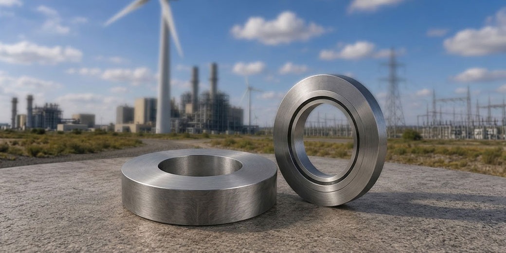
Seamless rolled rings are among the highest-volume and highest-value forging categories in the US wind and energy sector. Tower flanges, main bearing rings, pitch and yaw bearing rings, wind turbine hub structural rings, gas turbine casing rings, steam turbine diaphragm rings, and pressure vessel structural rings are all produced by ring rolling — a forging process that produces near-net-shape circular forgings with circumferential grain flow that cannot be achieved by any other manufacturing method. Indian ring rolling manufacturers with radial-axial ring rolling mills, AS9100D certification, and demonstrated capability across structural steel, alloy steel, stainless steel, and nickel alloy ring rolling are positioned to supply the US wind and energy sector at 20–35% cost advantage over domestic US and European ring rolling supply.
At a Glance: Ring Rolling Applications in US Wind and Energy
| Application | Material | OD Range | Weight | Key Requirement |
| Wind tower base flange | S355NL | Ø2,500–5,000mm | 800–4,000 kg | Charpy -20°C, flatness ±1mm |
| Wind tower intermediate flange | S355NL | Ø2,000–4,000mm | 500–2,000 kg | Same |
| Main bearing outer ring blank | 42CrMo4 | Ø1,500–4,000mm | 500–5,000 kg | Hardness uniformity, 100% UT |
| Pitch bearing ring blank | 42CrMo4 | Ø1,000–3,000mm | 200–2,000 kg | Same |
| Yaw bearing ring blank | 42CrMo4 | Ø1,500–3,500mm | 300–2,500 kg | Same |
| Gas turbine casing ring | Inconel 625, alloy steel | Ø500–2,500mm | 200–3,000 kg | UT, dimensional |
| Steam turbine diaphragm ring | CrMoV, 410 SS | Ø500–2,000mm | 100–2,000 kg | Face flatness, UT |
| Pressure vessel nozzle ring | A182 F316L, F51 | Ø300–1,500mm | 50–800 kg | Material certification |
| Nuclear structural ring | SA-508 Gr.3, F316L | Ø300–1,000mm | 100–1,000 kg | NQA-1, full traceability |
What Ring Rolling Is and Why It Cannot Be Replaced
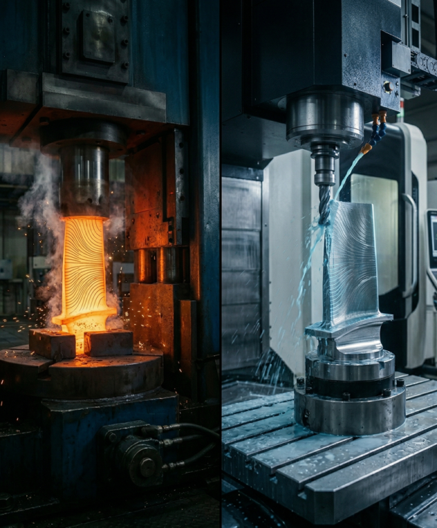
Ring rolling is a hot forming process that converts a hollow preform (a ring-shaped billet with a central bore) into a finished ring of larger diameter and reduced cross-section by simultaneous radial and axial reduction between driven rolls. The radial roll reduces the wall thickness while the axial rolls control the ring height the process continues until the ring reaches the specified diameter, wall thickness, and height.
Why circumferential grain flow is the critical advantage: When a ring is ring-rolled, the metal flows circumferentially the grain structure orients along the ring’s circumference. This means:
- The highest-strength grain direction (longitudinal) runs around the ring
- Hoop stress the primary loading in most ring applications is resisted by the strongest grain direction
- Fatigue crack initiation and propagation resistance are maximised in the circumferential direction
A ring cut from a plate or bar has interrupted grain flow at the cut edges the strongest grain direction runs through the material in a straight line, not around the ring. Under internal pressure or bolt preload, plate-cut rings are 15–30% weaker in the hoop direction than equivalent ring-rolled forgings which is why ring rolling is the mandatory manufacturing process for pressure vessel flanges, wind tower flanges, and rotating machine rings in any safety-critical application.
Radial-Axial Ring Rolling: The Process That Makes Large Rings Possible
How Radial-Axial Ring Rolling Works
A radial-axial ring rolling mill the type used for all structural and precision ring rolling in energy, wind, and industrial applications uses four rolls:
Main roll (drive roll): The large outer roll that drives the ring rotation. The main roll applies radial reduction force squeezing the ring wall thinner as the diameter grows.
Mandrel roll (inner roll): A smaller roll on the inside of the ring that provides counter-pressure to the main roll. The gap between the main roll and mandrel roll determines the wall thickness being formed.
Axial rolls (cone rolls): Two rolls above and below the ring that control the ring height. Without axial rolls, ring rolling produces a ring that spreads uncontrolled in the axial direction the axial rolls confine this spread to achieve the specified ring height.
Guide rolls: Two opposing guide rolls that maintain ring roundness as the diameter increases. Without guide rolls, the ring becomes oval as it grows.
The combination of simultaneous radial and axial reduction under controlled roll forces controlled by a CNC system on modern mills produces rings that are dimensionally consistent, metallurgically sound, and near-net-shape ready for machining.
Ring Rolling Mill Capacity Parameters
Ring rolling mill capacity is defined by several parameters that determine what rings can be produced:
Maximum ring OD: The largest outer diameter the mill can produce limited by the mill’s main roll diameter and the guide roll spread. Vinir’s Wagner and Banning mill produces rings to Ø4,500mm OD.
Maximum ring height: The axial dimension of the ring – limited by the axial roll spread. Taller rings require greater axial roll capacity.
Maximum ring weight: Limited by the preform handling system and the mill’s rolling force capacity. At Vinir’s mill, maximum ring weight is approximately 8,000 kg.
Material capability: The mill’s heating system and roll materials determine which alloys can be rolled. Carbon and structural steels, alloy steels, stainless steels, duplex and super duplex, Inconel 625 and 718, titanium all require different forging temperatures and different roll materials.
Wind Tower Flange Ring Rolling: The Highest-Volume US Opportunity
Process for S355NL Wind Tower Flanges
Billet preparation: The starting material is an S355NL round billet, cut to the calculated weight that will produce the specified ring after rolling accounting for scale loss and any trimming. The billet is through-heated in a gas-fired furnace to the forging temperature range for S355NL (1,100–1,250°C) with adequate soak time to achieve temperature uniformity through the section.
Upsetting and piercing: The heated billet is upset on a press compressed axially to increase diameter and reduce height. The upset billet is then pierced by a press punch to create the central bore this produces the hollow preform (donut shape) from which ring rolling begins.
Ring rolling: The preform is placed on the mandrel roll and ring rolling begins. The main roll applies radial force; the axial rolls apply axial force to control height; the guide rolls maintain roundness. The rolling continues until the ring reaches the target OD, wall thickness, and height as measured by a diameter gauge or laser measuring system.
Heat treatment: S355NL wind tower flanges are normalised after ring rolling heated to 890–920°C and air cooled. The normalising cycle refines the grain structure disrupted by rolling and develops the mechanical properties required by EN 10025-3.
Charpy impact testing at -20°C: Every wind tower flange lot requires Charpy impact testing at -20°C the distinguishing requirement of the NL designation. Specimens are taken from the ring in the tangential direction (circumferential), as this represents the primary loading direction for hoop-stressed flanges. Minimum 27 J average per EN 10025-3.
Dimensional inspection: Face flatness is the critical post-machining dimension for wind tower flanges. Laser flatness measurement or CMM verification confirms the face is within ±1mm across the full face diameter. Tower section joints that are not flat create uneven bolt loading that initiates fatigue cracking at the bolted joint the most common structural failure mode for wind tower flanged connections.
Offshore Wind Tower Flange Requirements
Offshore wind tower flanges in the Ø4,000–6,000mm range for 10–15 MW turbines are among the largest ring-rolled structural forgings produced anywhere in the world. Vinir’s mill at Ø4,500mm maximum covers offshore turbines up to approximately 8–10 MW. The emerging 12–15 MW offshore turbine class (Siemens Gamesa SG 14-236, Vestas V236-15 MW, GE Haliade-X 13 MW) requires tower base flanges above Ø5,000mm beyond current Indian ring rolling mill capacity and requiring a mill investment decision.
For the current US offshore wind development pipeline Vineyard Wind (SG 14-236 DD), South Fork Wind (SG 11-200 DD, Ø3,500–4,000mm tower flanges), Revolution Wind (GE Haliade-X 12 MW, Ø4,200–4,500mm tower flanges) Vinir’s Ø4,500mm mill covers the flange diameter range for several active US offshore wind projects.
Bearing Ring Rolling for US Wind Turbines
Main Bearing Ring Rolling Process
The main bearing outer ring for a 5 MW direct-drive wind turbine has an OD of approximately 3,500–4,500mm and a weight of 3,000–6,000 kg at the top end of Indian ring rolling capability.
Material: 42CrMo4 (SAE 4140) alloy steel
The ring rolling process for bearing rings differs from structural steel rings in one critical aspect the surface that will become the bearing raceway must be protected during rolling. If the raceway surface oxidises during ring rolling (forming a scaled surface), the scale removal during machining may not fully clean the surface before induction hardening leaving scale inclusions that fracture under rolling contact stress in service.
Scale control during rolling: Bearing ring rolling requires controlled-atmosphere heating or minimised heating time to reduce scale formation on the surfaces that will become the raceway. Some ring rolling mills use induction heating for bearing ring billets faster heating reduces total time at temperature and therefore scale formation. Post-rolling pickling or shot blasting removes surface scale before machining.
Hardness uniformity verification: Through-hardened bearing rings require hardness verification at multiple circumferential positions minimum 8 positions around the ring, at multiple depth positions through the wall section. Hardness variation above 3 HRC between positions indicates uneven quench cooling. The quench tank for bearing ring heat treatment must have mechanical agitation sufficient to ensure uniform cooling around the ring circumference.
100% UT before delivery: All main bearing and pitch bearing ring forgings for US wind OEMs (Vestas, GE Vernova, Siemens Gamesa) require 100% volumetric UT before delivery. The UT reference standard must be in 42CrMo4 alloy steel at the same heat treatment condition. Subsurface inclusions that escape detection in the as-rolled condition will propagate to the raceway surface after induction hardening causing premature bearing failure.
Gas Turbine Casing Ring Rolling
Material and Process
Gas turbine combustor casings, compressor exit casings, and turbine inlet casings are fabricated from ring-rolled forgings in Inconel 625 (for high-temperature hot section casings) or alloy steel (for lower-temperature compressor casings).
Inconel 625 ring rolling: Inconel 625 is ring-rolled in the temperature range 900–1,175°C. The flow stress of Inconel 625 at forging temperature is approximately 3× that of carbon steel requiring significantly higher rolling forces for equivalent ring geometry. The mandrel roll and main roll must be made from hot work tool steel that resists the higher contact pressures of nickel alloy rolling.
After ring rolling, Inconel 625 casing rings are solution annealed at 1,093–1,204°C with rapid water quenc the same heat treatment as Inconel 625 forgings of any geometry. The solution anneal dissolves delta phase and Laves phase formed during rolling and restores the fully solid-solution-strengthened microstructure.
Alloy steel compressor casing rings: For lower-temperature compressor casings in 4340 or CrMoV alloy steel, the ring rolling process is straightforward standard carbon or alloy steel rolling practice. Heat treatment after rolling normalise and temper for structural grades, quench and temper for high-strength grades is performed in AMS 2750-calibrated furnaces.
Steam Turbine Diaphragm Ring Rolling
Why Flatness Is the Critical Requirement
Steam turbine diaphragms the fixed stator elements between rotating turbine stages are mounted in diaphragm rings that must mate precisely with the turbine casing bore and with the adjacent diaphragm rings. The flatness of the diaphragm ring faces directly determines whether steam leaks past the diaphragm in service leakage reduces turbine efficiency and can cause erosion of the diaphragm and casing.
Dimensional requirements for diaphragm rings:
- Face flatness: ≤0.2mm total across the full ring face diameter
- Face parallelism (two faces parallel to each other): ≤0.15mm
- Bore roundness: ≤0.3mm OD variation around the circumference
- Wall thickness uniformity: ≤1.5% variation around the circumference
Achieving these tolerances requires:
- Ring rolling to near-net dimensions with tight process control
- Slow, controlled machining of the ring faces to avoid introducing thermal distortion
- Face flatness verification by CMM or precision laser measurement after machining
Material for diaphragm rings: CrMoV alloy steel for high-pressure and intermediate-pressure steam turbine diaphragm rings where creep resistance at elevated steam temperature is required. 410 martensitic stainless steel for low-pressure turbine diaphragm ring where condensed steam creates corrosion conditions that CrMoV cannot resist without coating.
Pressure Vessel and Nuclear Structural Ring Rolling
ASME B16.47 Large Diameter Flange Rings
Large-diameter pipeline flanges to ASME B16.47 Series A and Series B – NPS 26 through NPS 60 are produced as ring-rolled blanks in carbon steel (ASTM A105, ASTM A694 F65/F70) and stainless steel (ASTM A182 F316L, F51 duplex). The ring-rolled blank is subsequently machined to B16.47 dimensional tables raised face or RTJ groove profile and UT inspected before delivery.
US oil and gas pipeline construction – including the expanding US LNG export infrastructure and the Permian Basin / Eagle Ford gathering system expansion generates ongoing demand for large-diameter B16.47 ring-rolled flanges in the NPS 26–60 range.
Nuclear Structural Rings
ASME Section III nuclear structural rings seal rings, support rings, and structural connector rings for reactor systems are ring-rolled in SA-182 F316L austenitic stainless or SA-508 Grade 3 alloy steel under NQA-1-compatible quality controls. The ring rolling process documentation for nuclear supply includes: billet material traceability to VIM/VAR MTR, rolling temperature records, heat treatment furnace chart with AMS 2750 calibration reference, UT report with SA-508 Grade 3 calibration standard reference, and CoC with all required specification references.
Quality Requirements for US Energy Sector Ring Rolling Supply
Dimensional Verification Methods
Laser diameter measurement during rolling: Modern ring rolling mills use laser diameter gauging that measures the ring OD continuously during rolling providing real-time feedback to the CNC control system. This allows the rolling process to stop at exactly the target OD without manual measurement interruption.
CMM inspection of machined rings: All critical-dimension ring forgings for US energy sector supply require CMM verification after machining. CMM reports for wind tower flanges show: face flatness map, bore roundness, OD roundness, wall thickness at minimum 8 circumferential positions, and bolt hole position (where applicable).
Ring squareness: The bore axis must be perpendicular to both ring faces within specified tolerances. Squareness is measured by CMM – the face plane and bore axis are measured and the angle between them calculated.
TPI for US Energy Sector Ring Rolling
Bureau Veritas and DNV GL are the primary inspection companies for ring-rolled forgings supplied to the US energy sector:
Wind OEM inspection: Vestas, GE Vernova, and Siemens Gamesa specify their approved TPI companies in the purchase order. Bureau Veritas and DNV GL are universally on these approved lists. The inspector witnesses: heat treatment (furnace chart review and hardness verification), Charpy impact testing, and final dimensional inspection.
Nuclear ring inspection: N-Certificate holder oversight as described in the nuclear blogs in this series hold point management with notification, independent inspection, and documentation package review before CoC issuance.
Vinir Engineering’s Ring Rolling Capability for US Energy Supply
Wagner and Banning radial-axial ring rolling mill: Maximum OD: Ø4,500mm. Maximum ring height: 500mm. Maximum ring weight: 8,000 kg. Material capability: carbon steel, alloy steel, stainless steel (all grades), duplex 2205, super duplex 2507, Inconel 625, Inconel 718, Ti-6Al-4V.
Wind tower flanges: S355NL rings to Ø4,500mm. NABL-accredited Charpy impact at -20°C. Face flatness verification by CMM after machining. TPI by Bureau Veritas or DNV per OEM specification.
Bearing rings: 42CrMo4 through-hardened bearing ring blanks. Hardness uniformity at minimum 8 circumferential positions per ring. 100% UT with 42CrMo4 calibration standard. Scale-minimised heating practice for raceway surface protection.
Gas turbine casing rings: Inconel 625 solution annealed with rapid water quench. Alloy steel normalised or Q&T per specification. UT with alloy-specific calibration standards.
Steam turbine diaphragm rings: CrMoV and 410 stainless. Face flatness ≤0.2mm verified by CMM. Precision machining with thermal distortion control.
Nuclear structural rings: SA-182 F316L and SA-508 Grade 3 under NQA-1-compatible quality controls. Full traceability from VIM/VAR MTR through delivery.
AS9100D: Full scope including ring rolling, heat treatment, NDT, and machining. NABL-accredited in-house testing. TPI through Bureau Veritas and DNV GL.
Lead times: Carbon and alloy steel rings 8–12 weeks to US port. Stainless and duplex 10–14 weeks. Inconel 625 – 14–18 weeks (including raw material procurement from Special Metals). All lead times include ocean freight from Chennai to US Gulf or East Coast.