
First Article Inspection for Aerospace Forgings in India: AS9102 Requirements and FAIR Package
First article inspection for aerospace forgings is the mandatory verification process applied to the first production sample of every new forged component entering an aerospace supply chain. It is not a standard incoming inspection — it is a comprehensive, documented comparison of the manufactured component against every requirement of the engineering drawing, material specification, and quality plan. In India, aerospace OEMs including HAL, DRDO programme offices, and international OEM offset programmes all require first article inspection to AS9102 standards before any new forging part number enters production supply.
What First Article Inspection Is and Why It Exists
First article inspection exists because engineering drawings and manufacturing processes are both imperfect. A drawing may contain ambiguities that the designer did not intend. A manufacturing process may produce a component that meets every individual process parameter but misses a dimension that no individual process step directly controls. The forging die may produce a slightly different geometry than the CAD model predicted.
FAI catches all of these disconnects before they become production problems. By verifying every drawing requirement against the actual manufactured component before production approval is granted, the OEM confirms that:
- The drawing can actually be manufactured to — every dimension is achievable with the current process
- The supplier has correctly interpreted every drawing requirement — no misread tolerances, no missed key characteristics
- The material meets all specification requirements — chemistry, mechanical properties, cleanliness
- The special processes (heat treatment, NDT) were qualified and executed correctly
- The documentation system produces complete and consistent records
A FAIR-approved forging part number can go into production with confidence that the process is correct. A forging that goes into production without FAI may contain systematic errors that affect every subsequent component — and that are not discovered until an OEM quality inspection rejects an entire batch, or worse, until a component fails in service.
At a Glance: AS9102 FAIR Forms for Aerospace Forgings
| Form | Title | Applicability to Forgings |
| Form 1 | Part Number Accountability | Always required — identifies the part and its design documentation |
| Form 2 | Product Design Documentation | Always required — confirms drawing revision and spec applicability |
| Form 3 | Engineering Drawing Inspection | Always required — every dimension measured and recorded |
| Form 4 | Design Characteristic Accountability | Always required — all key characteristics identified and inspected |
| Form 5 | Material/Raw Material Test Results | Always required — MTR and independent chemical analysis |
| Form 6 | Dimensional Test Results (special) | Required where Form 3 is insufficient for complex geometry |
| Form 7 | Functional Test Results | Required where functional testing is specified |
| Form 8 | Certificate of Conformance | Always required — supplier’s formal declaration |
| Form 9 | Special Process(es) Certificate | Always required for forgings — heat treatment, NDT procedures |
| Form 13 | Other Tests and Inspections | Required where additional testing is specified (fatigue, etc.) |
Forms 10, 11, 12, and 14 cover software, safety, statistical data, and sub-tier supplier documentation respectively — applicability depends on the specific programme requirements.
Form 1: Part Number Accountability
Form 1 establishes the identity of the first article — what it is, who made it, and under which design authority.
Required information :
- Part number and dash number (if applicable)
- Part name as shown on the drawing
- Drawing number and revision letter
- Customer name and programme
- Supplier name, address, and AS9100D certificate number
- Date of first article submission
- Ballooned drawing reference — the marked-up drawing that links every dimension to a Form 3 balloon number
Common failure: Submitted Form 1 references a drawing revision that differs from the current revision in the OEM’s document control system. This occurs when the supplier was issued an earlier drawing revision during initial development and did not receive the current revision before manufacturing. The FAIR is rejected for drawing revision mismatch and resubmission requires manufacturing another first article to the current drawing revision.
Form 2: Product Design Documentation
Form 2 lists every document that governs the manufacture and acceptance of the forging — the drawing, all referenced specifications, all customer-specified quality plan requirements, and all notes on the drawing that reference external documents.
For a typical aerospace forging, Form 2 references may include :
- The part drawing (number and revision)
- Material specification (AMS 4928 for Ti-6Al-4V, AMS 5663 for Inconel 718)
- Heat treatment specification (AMS 2770 for aluminium, customer-specific for titanium and Inconel)
- NDT specification (AMS 2647 for FPI, AMS 2154 for UT)
- Forging specification (AMS 2374 for aluminium forgings, customer-specific for titanium)
- Surface finish specification (where referenced on drawing)
- Customer quality plan document number and revision
Common failure: A specification referenced on the drawing is listed in Form 2 at a superseded revision. The supplier used an older version of the specification without verifying that the current revision was in use. This is a finding that requires review of whether the superseded revision imposed different requirements — if yes, the component may not meet current requirements.
Form 3: Engineering Drawing Inspection — The Core of the FAIR
Form 3 is where every dimension on the drawing is measured, recorded, and compared to the nominal and tolerance values. This is the most time-consuming element of the aerospace forging FAIR and the one most likely to contain findings.
Ballooning the Drawing
Before measurement begins, the drawing is balllooned — every dimension, note, and requirement is assigned a sequential balloon number. The balloon numbers on the marked-up drawing correspond to the line items on Form 3. Every balloon number appears exactly once on the drawing and exactly once on Form 3.
Ballooning is itself a skill — identifying every requirement on a complex aerospace forging drawing without missing any feature or note, without assigning the same number to two features, and without losing track of common requirements that apply to all features (general tolerances, surface finish notes) versus feature-specific requirements.
Common ballooning errors:
- Missing a general tolerance note — the note applies to all undimensioned features but was not ballooned and therefore not inspected
- Missing a note that specifies a material or process requirement — the note says “material per AMS 4928, heat per AMS 2770” but was not ballooned and the heat treatment was not referenced in Form 9
- Applying a specific tolerance to a feature when the drawing uses the general tolerance — a dimension measured to the wrong tolerance band
Measurement Methods and Equipment
For each ballooned dimension, Form 3 records :
- The balloon number
- The nominal value and tolerance from the drawing
- The actual measured value
- The measurement method and equipment used (CMM, outside micrometer, pin gauge, etc.)
- Pass/fail status
Equipment calibration — every measuring instrument used in the FAIR must be on a current calibration cycle with traceable calibration. The instrument serial number and calibration due date are typically noted on the FAIR or available on request. An instrument found to be out of calibration during the FAIR makes all measurements made with that instrument suspect — the FAIR must be repeated with calibrated equipment for the affected dimensions.
Statistical uncertainty — for high-precision aerospace dimensions measured close to the tolerance limit, measurement uncertainty may need to be considered. If a dimension is measured at the very edge of tolerance, the measurement uncertainty must be smaller than the tolerance to give confidence in the result. AMS-qualified dimensional inspection includes consideration of measurement uncertainty for key characteristics.
Key Characteristics on Form 3 and Form 4
Key characteristics — dimensions and properties designated safety-critical in the design — receive special treatment in the FAIR. They are identified on the drawing (typically with a special symbol — a triangle, diamond, or KC designation), listed on Form 4, and 100% inspected on every first article component. Form 4 lists every key characteristic with the inspection method, the acceptance criterion, and the results.
For aerospace forgings, key characteristics typically include :
- Critical structural dimensions — minimum wall thickness in a structurally loaded section
- Bore concentricity on disc and ring forgings — critical for balance in rotating applications
- Surface finish on mating or sealing surfaces
- Grain size (where specified) — for engine rotating components
Form 5: Material and Raw Material Test Results
Form 5 records the material traceability and test results that confirm the forging material meets the applicable specification.
Required content for aerospace forgings:
Raw material certification:
- Material specification (AMS number) and revision
- Alloy designation and temper/condition
- Mill name and location
- Heat or lot number
- Mill test report attached — showing chemistry against specification limits and mechanical properties from the mill’s own testing
Independent chemical analysis :
- Results from the supplier’s own NABL-accredited lab spectrographic analysis
- Compared to specification limits
- Referenced to the same heat number as the MTR
Mechanical test results :
- Tensile test (UTS, yield, elongation, reduction of area) from a witness coupon forged from the same heat
- Charpy impact (where specified)
- Hardness (where specified)
- All results compared to specification minimum values
- Test method referenced (ASTM E8 for tensile, ASTM E23 for Charpy)
Common failure: Form 5 mechanical test results are from the as-forged condition but the specification requires testing in the heat-treated condition. This occurs when the supplier tests a witness coupon before heat treatment and submits those results. The test must be conducted after final heat treatment — the condition in which the forging will be used.
Form 9: Special Process Certificates
Form 9 is critical for aerospace forgings because heat treatment and NDT are both special processes. The form requires evidence that each special process was performed to a qualified procedure by qualified personnel on qualified equipment.
Heat treatment certificate content :
- Heat treatment procedure number and revision
- Furnace identification number
- AMS 2750 compliance evidence — TUS record number and date, confirming the furnace was within calibrated temperature uniformity limits at the time of the heat treatment
- Thermocouple calibration certificate number and expiry
- Load temperature profile (furnace chart) showing the complete cycle — attached or referenced
- Hardness test result after heat treatment
- Operator name and qualification reference
NDT certificate content :
- NDT procedure number, revision, and technique (contact UT, immersion UT, FPI, MT)
- Equipment identification and calibration certificate reference
- Reference standard used for UT calibration — serial number and material specification
- Acceptance criterion — AMS 2154 class, or customer-specific level
- Inspector name, ASNT certification level and number, expiry date
- Result — pass/fail with any relevant indications and disposition
- FPI system qualification records (for titanium and aluminium) — penetrant type, sensitivity level, UV lamp intensity
Common failure: The NDT procedure referenced in Form 9 is a generic procedure for the method, not a programme-specific procedure approved by the OEM. Most aerospace OEMs require that the specific NDT written practice for their programme is submitted and approved before the FAIR. A FAIR submitted with a generic “UT procedure for steel forgings” rather than an OEM-approved procedure for the specific component is rejected.
Form 8: Certificate of Conformance
Form 8 is the supplier’s formal declaration that the first article component conforms to the drawing, all referenced specifications, and the quality plan. It is signed by the quality manager — typically the Management Representative or Quality Director — and accompanied by their name, title, and authority reference.
The CoC is the legal document of the FAIR — it commits the supplier to the conformance claim. Any subsequent finding that the first article did not actually conform to a requirement constitutes a quality escape from the FAIR process, which is a serious finding in HAL and CEMILAC programmes.
Common FAIR Rejection Reasons in Indian Aerospace Forging
Based on FAIR submissions reviewed by HAL and defence aerospace OEM quality teams, the most frequent rejection reasons for aerospace forging FAIRs from Indian suppliers are:
Drawing Revision Mismatch
The FAIR is prepared to an earlier drawing revision than the current approved revision. The supplier was issued the drawing in development and did not receive the update before manufacturing. Prevention: confirm drawing revision directly with the OEM’s drawing control system immediately before manufacturing begins, not when drawing was received during development.
Missing Dimensions on Form 3
Not every drawing dimension was ballooned and measured.
This typically occurs when :
- A note on the drawing references a dimension that is not explicitly shown with a dimension line — for example, “minimum web thickness 8mm” in a general note rather than a dimensioned feature
- A general tolerance applies to an unspecified feature and was not listed on Form 3
- A view in the drawing contains a dimension that is obscured or easily overlooked
Prevention: systematic ballooning review by a second person unfamiliar with the drawing who can identify what a first reviewer missed.
Key Characteristics Not Identified
Form 4 is missing or incomplete — not all features designated as key characteristics on the drawing were identified and given 100% inspection treatment. This occurs when the supplier does not understand the OEM’s key characteristic designation system or when key characteristics are identified using a symbol the supplier did not recognise.
Prevention: clarify the key characteristic designation system with the OEM before drawing interpretation. HAL uses a specific symbol that is defined in their supplier documentation standards.
Heat Treatment Records Incomplete
The furnace chart is missing the controlled cooling section between ageing stages (Inconel 718) or shows a temperature excursion that was not formally dispositioned. The thermocouple calibration certificate attached to Form 9 has an expiry date that falls before the heat treatment date.
Prevention: verify all heat treatment records are complete and cross-referenced before assembling Form 9. Thermocouple calibration certificates should be current for the entire heat treatment period — not just current at the time of FAIR submission.
Independent Chemistry Not Matching MTR
The supplier’s NABL lab independent chemistry analysis shows one or more elements outside the specification limits, while the mill MTR shows conforming values. This can indicate: different sampling locations (the mill tested from a different part of the heat), analytical error in one lab, or a genuinely non-conforming heat that the mill’s analysis missed.
The appropriate response is a hold on the first article pending investigation, not submission of the FAIR with a known discrepancy.
FAIR Turnaround Time: What Aerospace OEMs Expect
Aerospace OEMs expect FAIR packages to be submitted within a defined time after the first article is manufactured — typically 30 days for standard complexity forgings, up to 60 days for complex components requiring fatigue or functional testing.
FAIR review time at HAL and defence aerospace OEMs — the time from submission to approval or return with findings — typically takes 4–8 weeks for standard forging FAIRs. Complex FAIRs, or those with findings requiring resubmission, take 3–6 months.
Suppliers who submit incomplete or poorly prepared FAIRs effectively extend their own qualification timeline — HAL will not approve a FAIR with missing forms or unresolved findings. Each FAIR rejection and resubmission cycle adds 4–8 weeks to the qualification timeline.
Vinir Engineering’s FAIR Capability
Vinir Engineering’s quality team is experienced in AS9102 FAIR package assembly across titanium, Inconel, alloy steel, and aluminium aerospace forgings.
The FAIR process at Vinir covers:
- Systematic drawing ballooning reviewed by two quality engineers
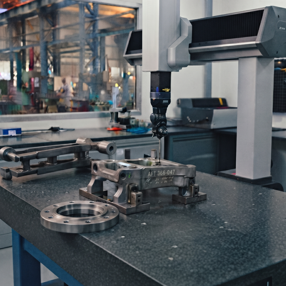
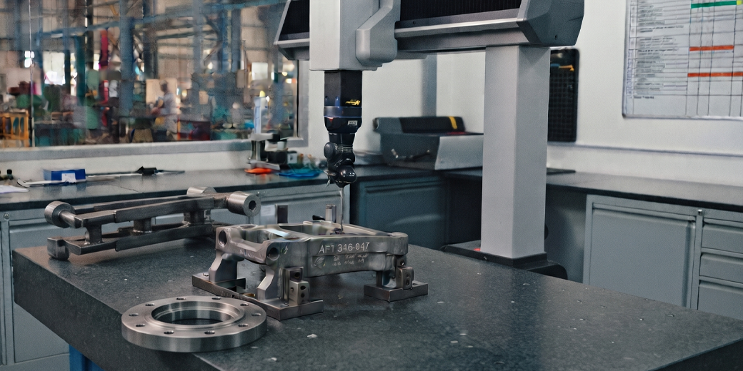
- CMM dimensional inspection with full recording of actual values against tolerances
- NABL-accredited in-house chemistry and mechanical testing to ASTM methods
- Complete heat treatment records — AMS 2750 compliant furnace charts, thermocouple calibration current at time of manufacture
- FPI to AMS 2647 and UT inspection documented to AS9100D-approved written procedures
- Form 9 special process certificates cross-referenced to current approved procedures
- Quality manager signed CoC with authority reference
For programme offices and supply chain managers planning first article programmes with Vinir, the FAIR package can be submitted within 25 working days of forging completion for standard complexity components.
Frequently Asked Questions — First Article Inspection Aerospace Forgings India
What is AS9102 and how does it relate to AS9100D?
AS9102 is the First Article Inspection standard — a separate document from AS9100D that defines the requirements for first article inspection reports in aerospace. AS9100D (the quality management system standard) requires that first article inspection is performed for new part numbers. AS9102 defines specifically what the FAIR must contain — the forms, the measurement requirements, the documentation structure. A supplier with AS9100D certification has an obligation to perform FAI; AS9102 defines how to document it. Both standards are required for a credible aerospace forging supply programme.
Is first article inspection required every time a new part number is manufactured?
Yes — every new part number requires a FAIR before production supply begins. Additionally, a new FAIR is required when there is a significant change to an existing part number — drawing revision that adds or changes dimensions, change in material specification or heat treatment specification, change in manufacturing location or process. The definition of “significant change” triggering FAIR resubmission is specified in the customer’s quality plan, but material changes and process changes at special process level almost always require FAIR resubmission.
What is a ballooned drawing and how is it used in the FAIR?
A ballooned drawing is a marked-up copy of the engineering drawing where every dimension, tolerance, note, and requirement is assigned a sequential number enclosed in a circle (balloon). The balloon numbers directly correspond to line items on FAIR Form 3, creating a direct traceability link between the drawing requirement and the measurement result. The ballooned drawing is submitted as part of the FAIR package. Reviewers use it to verify that every drawing requirement was identified, ballooned, and has a corresponding measurement result on Form 3.
What happens if a dimension on the FAIR Form 3 is outside tolerance?
An out-of-tolerance dimension on Form 3 is a FAIR finding. The supplier cannot approve their own FAIR with known out-of-tolerance dimensions. Options are: scrap the first article and manufacture another, rework the first article within allowed rework limits (not all dimensions can be reworked — machining to a tighter dimension is possible, but a dimension that is too small cannot be corrected), or submit a deviation request to the OEM’s engineering team explaining why the out-of-tolerance condition is acceptable for a specific reason. Deviation requests for structural aerospace dimensions are rarely approved without significant engineering justification.
How long does a typical aerospace forging FAIR take to prepare?
Preparation time for an aerospace forging FAIR depends on component complexity. A simple forging with 20–30 drawing dimensions, straightforward material, and standard heat treatment takes approximately 10–15 working days after the forging is complete — including dimensional measurement, lab testing, documentation assembly, and quality manager review. A complex forging with 80–100 drawing dimensions, titanium material requiring alpha case verification, and multiple NDT methods takes 20–30 working days. A FAIR requiring functional testing (burst pressure, fatigue) takes substantially longer depending on the test duration and lab availability.