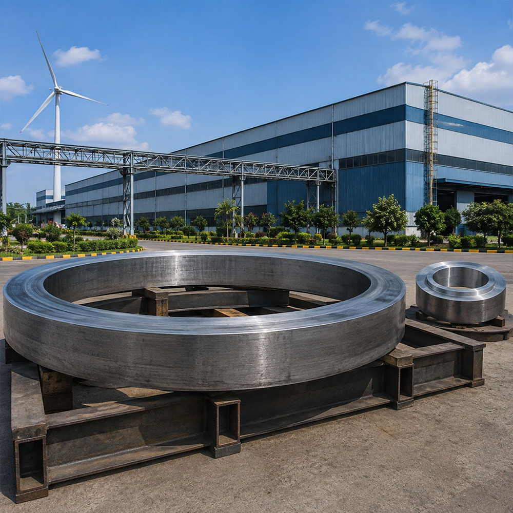
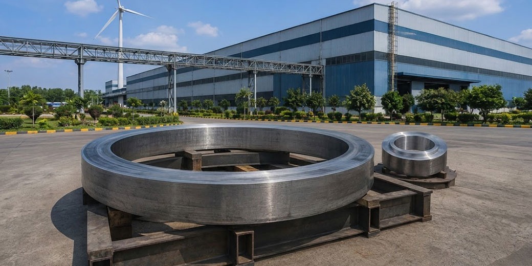
Ring rolling — the process of rolling a ring-shaped preform between driven rolls to progressively reduce wall thickness and increase diameter is the mandatory manufacturing method for all circular cross-section components requiring circumferential grain flow: wind turbine tower flanges, pressure vessel flanges, bearing rings, turbine casing rings, and nuclear structural rings. Vinir’s Wagner and Banning radial-axial ring rolling mill at Bommasandra Unit 2 and Hosur Unit 4 produces seamless rolled rings to Ø4,500mm outer diameter in all standard alloy families supplying global wind OEMs, oil and gas operators, and marine customers at 20–35% cost advantage over European ring rolling supply.
Application
Material
OD Range
Certification
Wind turbine tower flange
S355NL EN 10025-3
Ø1,000–4,500mm
ISO 3834, BV/DNV survey
Offshore jacket structural ring
S355NL, S420NL
Ø500–4,500mm
DNV OS-C101, API 2B
Bearing ring (wind turbine slew)
42CrMo4 EN 10083
Ø500–3,000mm
ISO 6336, BV survey
Pressure vessel flange (API / ASME)
SA-105, SA-182 F316L, F51, F53
Ø300–4,500mm
API 20B, ASME B16.47, IBR
Turbine casing ring
CrMoV, EN 10269 Gr.30CrMoV9
Ø500–3,000mm
EN 10269, BV/Intertek survey
The ring rolling process begins with a ring-shaped preform a thick, short ring produced by open die upsetting and piercing of a heated billet. The preform is placed over the mandrel roll (inner roll that drives the ring rotation) and contacted by the main roll (outer roll that applies the radial reduction force). As the main roll presses against the ring, the wall thickness reduces and the ring diameter grows. Axial rolls (cone-shaped rolls contacting the ring’s top and bottom faces) control the ring height and prevent it from growing excessively tall.
The circumferential grain flow produced by ring rolling where the elongated grains align around the circumference of the ring is the fundamental structural advantage over all other ring-shaped component manufacturing methods. A flange produced by ring rolling has grains running circumferentially aligned with the hoop stress direction that the flange bolt pattern induces. A flange produced by machining from plate has grains running straight across the plate, providing the lowest toughness in the most critical direction.
Dimensional control during ring rolling is achieved by CNC control of the rolling mill rolls the main roll position controls wall thickness; the axial roll position controls ring height; and the OD guide rolls maintain ring roundness as the diameter grows. Modern CNC-controlled ring rolling mills like Vinir’s Wagner and Banning system achieve OD tolerances of ±0.5% of OD, wall thickness uniformity within ±3%, and height uniformity within ±2mm.
Vinir’s ring rolling mill covers the Ø200mm to Ø4,500mm OD range encompassing all onshore wind tower flanges (Ø1,000–3,000mm for 2–5 MW turbines), most offshore wind tower flanges (Ø3,000–4,500mm for 8–15 MW turbines), all pressure vessel flanges to ASME B16.47 Series B (Ø900mm maximum), and all oil and gas valve body structural rings to API 20B PSL 3. The Ø4,500mm upper limit positions Vinir at the boundary of the offshore wind flange market.
1.What is the difference between radial ring rolling and radial-axial ring rolling?+–
Radial ring rolling uses only the main roll (outer roll) and mandrel roll (inner roll) to reduce the ring wall thickness while the diameter grows the ring height is not actively controlled and tends to increase as wall thickness reduces. Radial-axial ring rolling adds axial rolls (cone-shaped rolls contacting the top and bottom faces of the ring) that actively control the ring height during rolling. Radial-axial ring rolling (Vinir’s Wagner and Banning mill is radial-axial) produces rings with more consistent height, better dimensional control, and the ability to produce rings with complex cross-section profiles (T-rings, L-rings, custom profile rings) by shaping the axial rolls to match the required profile.
2.What is the maximum ring rolling outer diameter achievable by Vinir and how does this relate to offshore wind turbine tower flange requirements?+–
Vinir’s Wagner and Banning ring rolling mill produces rings to Ø4,500mm OD covering all onshore wind tower flanges (Ø1,000–3,000mm for turbines up to approximately 6 MW), intermediate and upper tower section flanges for most offshore wind turbines (Ø3,000–4,500mm for turbines up to approximately 10–12 MW), and the full range of oil and gas and marine ring forging applications. Tower base flanges for the largest offshore turbines (Siemens Gamesa SG 14-236 DD, Vestas V236-15 MW) are Ø5,500–6,000mm above Vinir’s current capacity. However, the intermediate tower section flanges, transition piece flanges, and monopile top flanges for these same turbines are typically Ø3,500–4,500mm within Vinir’s range.
3.What dimensional inspection is required for rolled ring flanges per ASME B16.47 and API 20B?+–
ASME B16.47 (Large Diameter Steel Flanges) specifies dimensional requirements for flanges above DN 600 (24 inch). Critical dimensions include: OD and ID (to verify bore and flange OD tolerances), raised face OD and height, bolt circle diameter (BCD) with position tolerance on each bolt hole, flange face flatness (typically ±0.8mm for large flanges), and total face thickness. For API 20B ring-rolled flanges, additional requirements include PMI (for CRA grades), hardness verification (for sour service 4130M), and UT of each ring above a specified wall thickness threshold. Vinir performs CMM dimensional inspection for critical dimensions and maintains traceable inspection records for each ring forging shipment.
4.What is the Charpy impact test requirement for S355NL wind turbine tower flange forgings?+–
S355NL (EN 10025-3 normalised fine-grain structural steel) is the standard material for wind turbine tower flanges globally. The ‘L’ in S355NL designates ‘Low temperature’ the steel is impact tested at -50°C with minimum 27 J absorbed energy (average of 3 specimens, no individual value below 70% of the average). This -50°C test temperature ensures adequate toughness in the coldest expected operating conditions for offshore installations in the North Sea, Baltic Sea, or North Atlantic. Some offshore wind projects in sub-Arctic regions specify impact testing at -60°C as a supplementary requirement. Vinir’s NABL laboratory conducts Charpy testing at -50°C as a standard capability for wind energy forging programmes.
5.Why are ring-rolled flanges mandatory for high-pressure service and why cannot machined-from-plate flanges be substituted?+–
Ring-rolled flanges provide circumferential grain flow the elongated grains from the rolling process align around the circumference, parallel to the hoop stress direction that internal pressure and bolt preload generate. Machined-from-plate flanges have random grain flow relative to the flange geometry the through-thickness direction of the plate (the weakest direction) becomes the hoop stress direction of the flange. In high-pressure service, this through-thickness weakness creates preferential paths for laminar tearing at the flange root and hub. ASME Boiler and Pressure Vessel Code explicitly prohibits machined-from-plate flanges for Class 600 and above pressure service ring-rolled or forged flanges are mandatory above this pressure class.