Grain flow — the orientation of the elongated grain structure that forms during hot forging of steel, titanium, and nickel alloys is the fundamental metallurgical reason that forged components outperform machined-from-bar, cast, or additively manufactured equivalents in fatigue, fracture toughness, and creep resistance. Understanding grain flow is not just academic :aerospace buyers audit it via macro-etch sections in their First Article Inspection; oil and gas buyers require it documented in their API 20B qualification forgings; nuclear buyers require reduction ratio records that demonstrate adequate grain refinement through the full section. This technical blog explains the science behind grain flow and how Vinir controls it in critical-industry forgings.
Grain Flow Direction
Strongest For
Applications
Forging Process
Longitudinal (along axis)
Tensile, bending fatigue
Shaft forgings, connecting rods
Open die forging, extrusion
Circumferential (around ring)
Hoop stress, pressure containment
Pressure vessel flanges, bearing rings
Ring rolling
Contoured (following part shape)
Multi-axis fatigue, impact
Aerospace structural, turbine disc
Closed die forging
Radial (from centre outward)
Through-thickness properties
Disc forgings, valve bodies
Open die upset + closed die
When a steel billet is heated and pressed through a forging die or worked on a press, the grains originally equiaxed (roughly spherical) from the casting solidification elongate in the direction of metal flow. If the forging process is correctly designed, these elongated grains follow the contour of the component’s geometry running along the length of a shaft, circumferentially around a pressure vessel flange, or following the blade contour of a turbine disc web. This contoured grain flow is the defining structural advantage of forging over any other manufacturing process.
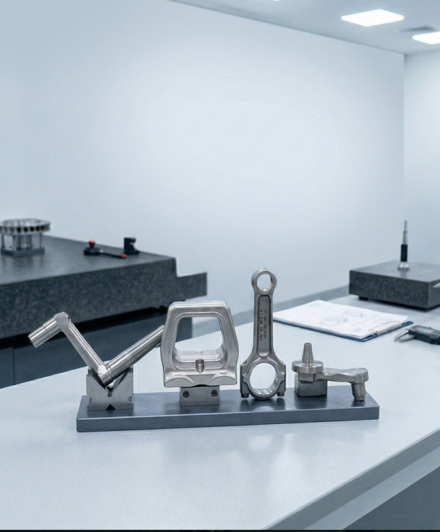
In a machined-from-bar component, the grain flow runs straight along the bar’s rolling direction — regardless of the component geometry. A connecting rod machined from bar will have grains running straight along the bar axis, crossing the highly-stressed small-end bore at 90° — the weakest orientation relative to the fatigue stress at that location. The same connecting rod produced by closed die forging has grains flowing around the small-end bore the strongest orientation. This grain flow difference is why virtually every critical connecting rod, crankshaft, and structural pin in the world is forged rather than machined.
Forging reduction ratio — the ratio of the original cross-sectional area to the final cross-sectional area is the quantitative measure of how much grain refinement has been achieved. A reduction ratio of 3:1 means the cross-sectional area has been reduced to one-third of its original value, requiring the grains to elongate significantly. At reduction ratios below 3:1, the grain structure may not be adequately refined the as-cast columnar grain structure of the ingot persists, reducing fatigue life and toughness. This is why minimum forging reduction ratios (typically 3:1 to 5:1 depending on application) are specified in forging engineering standards.
Macro-etch testing — immersing a cross-section of the forging in acid solution that preferentially attacks grain boundaries, revealing the grain flow pattern is the primary method of verifying grain flow in aerospace and critical industrial forgings. AS9102 FAIR (First Article Inspection Report) for aerospace structural forgings includes macro-etch documentation; API 20B PSL 3 qualification forgings require macro-etch or equivalent examination. At Vinir, macro-etch testing of qualification forgings is performed per ASTM E340 the acid-etch method for macrostructure examination of metals.
Forging process design with grain flow simulation using CAD/CAM analysis for critical die designs.
Macro-etch testing per ASTM E340 for aerospace FAIR and API 20B PSL 3 qualification forgings.
Reduction ratio documentation for all critical forgings recorded forging sequence showing area reduction at each working step.
Open die forging with manipulator control ensuring uniform reduction ratio through full section.
Ring rolling with laser OD measurement ensuring uniform wall thickness and consistent circumferential grain flow.
NABL laboratory for all mechanical testing referenced to grain flow direction (longitudinal, transverse, and circumferential specimens as required by OEM specification).
Frequently Asked Questions
1.What is macro-etch testing and how does it reveal grain flow in forgings?+–
Macro-etch testing involves cutting a cross-section from the forging (either from a test extension or from a production sample), surface-grinding the cut face to remove saw marks, then immersing the face in an acid solution — typically 50% hydrochloric acid at 70°C for steel, or a mixed acid solution for titanium and nickel alloys. The acid preferentially attacks grain boundaries and segregated areas, creating contrast that reveals the grain flow pattern at a macroscopic (naked-eye) scale. The resulting pattern shows: where grains flow along the component contour (desirable), where grain flow is interrupted or oriented across the stress direction (undesirable), and whether the as-cast segregation has been broken down by forging (indicated by absence of columnar grains from the original ingot solidification).
2.How does closed die forging produce better grain flow than open die forging for complex geometry components?+–
In open die forging, the metal flows under simple compression between flat or slightly shaped dies — the grain flow is primarily in the direction of metal spread (perpendicular to the press direction). For simple shapes (cylinders, shafts), this produces adequate longitudinal grain flow. For complex shapes (connecting rods, turbine disc webs, structural fittings), open die forging cannot produce grain flow that follows the contour — the metal flows to fill the available space rather than being guided to a specific geometric shape. Closed die forging uses a matched die set that precisely defines the finished shape — the metal is forced to flow into every corner of the die cavity, and the die geometry guides the flow so that grain lines follow the part contour. This is why virtually all aerospace structural and engine components are closed die forged.
3.What is anisotropy in forged components and how does testing direction affect reported mechanical properties?+–
Anisotropy means that mechanical properties differ depending on the measurement direction relative to the grain flow. In a forged shaft, tensile strength and fatigue life are highest in the longitudinal direction (along the grain flow, along the shaft axis) and lowest in the short transverse direction (across the grain flow, perpendicular to the shaft axis). This anisotropy is not a defect — it is inherent to the grain elongation that creates the forging’s structural advantage. However, it means that the direction of mechanical test specimens matters: specimens cut longitudinal (along grain flow) will show the best properties; specimens cut transverse will show lower values. Most forging specifications require testing in the longitudinal direction for primary properties and in the transverse direction for minimum toughness requirements — because the structure must perform in both orientations during service.
4.What is delta ferrite and why is it a grain flow concern in stainless steel forgings?+–
Delta ferrite is a body-centred cubic iron phase that forms in austenitic stainless steel (316L, 304L) during solidification from the melt. In the as-cast condition, delta ferrite appears as elongated streaks (stringers) within the austenite matrix. During forging, these delta ferrite stringers are broken up and redistributed — high reduction ratios (above 4:1) effectively fragment the continuous delta ferrite network into discrete particles that do not impair properties. Low reduction ratios (below 3:1) leave semi-continuous delta ferrite stringers that reduce toughness in the short transverse direction and create preferential corrosion attack paths in aggressive environments. For critical stainless steel pressure vessel forgings (API 20B PSL 3, NORSOK M-630), delta ferrite content is limited by specification and reduction ratio is documented to demonstrate adequate breaking up of the ferrite network.
5.How does Vinir document forging reduction ratio for critical oil and gas and nuclear forgings?+–
Vinir’s forging process documentation for critical forgings includes a forging sequence record — a step-by-step record of each press stroke or ring rolling pass showing: the initial billet dimension (diameter × length or OD × wall × height for rings), the dimension after each working step, the calculated cross-sectional area at each step, and the cumulative reduction ratio from the original billet to the finished forging. For open die shaft forgings, this record is maintained by the forge shop operator and reviewed by the quality inspector at each intermediate stage. For ring rolling, the rolling process is logged by the CNC control system — OD, wall thickness, and height are recorded at regular intervals during rolling. This complete forging sequence record is included in the documentation package for API 20B PSL 3 and nuclear NQA-1 forgings as evidence of process compliance.