Fatigue failure in forgings: crack initiation, propagation, and prevention
Fatigue Is the Silent Failure Mechanism in Critical Forged Components
Unlike overload fracture, fatigue failure does not require extreme stress.
It occurs under repeated cyclic loading — often well below the material’s ultimate tensile strength.
This makes fatigue particularly dangerous in forged components used in:
- Rotating shafts
- Turbine systems
- Pressure-retaining assemblies
- Railway axles
- Marine propulsion systems
- Heavy equipment connectors
- Aerospace structural brackets
A component may operate successfully for thousands or millions of cycles before microscopic damage accumulates and suddenly transitions into catastrophic fracture.
Fatigue failure is progressive, invisible in early stages, and often misdiagnosed as sudden failure.
Understanding fatigue requires examining how cracks begin, how they grow, and how they can be prevented through disciplined forging and process control.
Stage 1: Crack Initiation — Where Fatigue Begins
Fatigue cracks typically initiate at localized stress concentration points.
These may include:
- Surface machining marks
- Sharp geometric transitions
- Internal inclusions
- Micro-voids
- Corrosion pits
- Surface decarburization zones
Even small discontinuities can act as stress risers.
Under cyclic loading, microscopic slip bands form within the material’s crystal structure. Over time, these bands coalesce into microcracks.
In forged components, initiation sites are often influenced by:
- Grain orientation
- Surface finish quality
- Heat treatment uniformity
- Internal cleanliness of the material
Crack initiation is the longest phase of fatigue life. Proper process control can significantly delay this stage.
Stage 2: Crack Propagation — The Progressive Growth Phase
Once initiated, a fatigue crack grows incrementally with each stress cycle.
Propagation is influenced by:
- Stress amplitude
- Mean stress
- Material toughness
- Grain size
- Microstructural uniformity
In forged components with refined and aligned grain flow, crack propagation slows because grain boundaries resist crack movement.
Conversely, coarse or misaligned grain structures allow cracks to travel more easily.
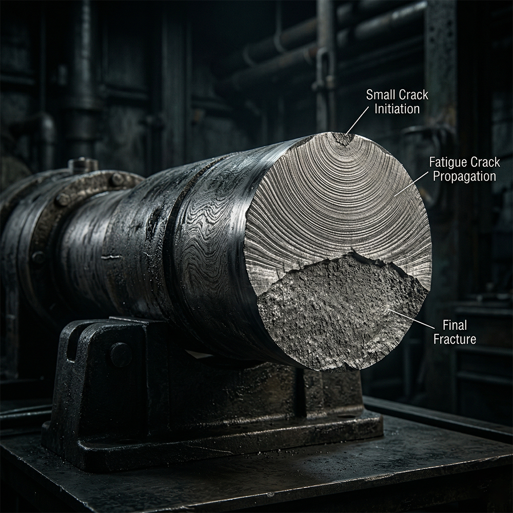
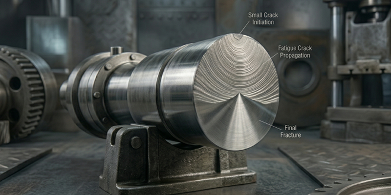
As propagation progresses, the effective load-bearing cross-section reduces until sudden fracture occurs.
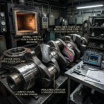
Often, fatigue fractures display characteristic “beach marks” or striations when examined under magnification — visible evidence of incremental crack growth.
Surface-Initiated vs Subsurface Fatigue
Fatigue failure in forgings can originate from two primary zones:
Surface-Initiated Fatigue
This is the most common type.
Surface defects such as:
- Rough machining
- Grinding burns
- Decarburization
- Corrosion
- Improper shot blasting
create stress concentration points.
In rotating components, tensile stress is highest at the surface, making this region particularly vulnerable.
Subsurface-Initiated Fatigue
In high-strength materials, especially under very high cycle conditions, cracks may originate below the surface.
Common causes include:
- Inclusions
- Non-metallic impurities
- Incomplete defect closure during forging
- Segregation zones
This highlights the importance of reduction ratio discipline and material cleanliness.
The Role of Reduction Ratio in Fatigue Resistance
Reduction ratio during forging directly influences fatigue performance.
Adequate deformation:
- Refines grain size
- Closes internal voids
- Breaks up segregation
- Improves homogeneity
Fine, uniform grain structures enhance crack resistance and slow propagation.
Insufficient reduction leaves internal structural inconsistencies that become crack initiation sites under cyclic stress.
Reduction is not merely a forging parameter — it is a fatigue resistance variable.
Grain Flow Engineering and Fatigue Life
Proper grain orientation aligned with the principal load direction significantly improves fatigue performance.
For example:
- Longitudinal grain in shafts improves torsional endurance.
- Circumferential grain in rings improves hoop stress resistance.
- Controlled fiber flow around fillet transitions reduces stress concentration impact.
Poor grain flow planning can create transverse grain boundaries across stress paths, accelerating crack growth.
Forging die design must consider final load conditions.
Heat Treatment and Fatigue Sensitivity
Heat treatment influences fatigue resistance through its effect on:
- Hardness
- Toughness
- Residual stress
- Microstructural uniformity
Excessively high hardness may increase brittleness, reducing fatigue life.
Residual tensile stresses introduced during quenching may accelerate crack growth.
Proper tempering and stress-relief cycles improve fatigue stability by balancing strength with toughness.
Thermal discipline is essential for cyclically loaded components.
The Impact of Surface Integrity
Surface condition has a disproportionate effect on fatigue life.
Factors influencing fatigue resistance include:
- Surface roughness
- Machining marks
- Micro-notches
- Oxide scaling
- Decarburization depth
In fatigue-critical applications, controlled surface finishing and post-processing techniques such as shot peening may be used to introduce beneficial compressive residual stresses.
Surface engineering is often as important as bulk metallurgical control.
Inspection and Fatigue Risk Management
Fatigue cracks in early stages are microscopic and not detectable through standard visual inspection.
However, prevention relies on:
- Ultrasonic testing to eliminate internal discontinuities
- Magnetic particle inspection for surface crack detection
- Controlled machining and surface finishing
- Strict documentation of reduction and heat treatment
Inspection is primarily preventive — ensuring that fatigue initiation sites are minimized before service begins.
Why Fatigue Failure Is Often Misattributed
In many failure investigations, fatigue fractures are mistaken for overload failures because the final fracture appears sudden.
However, metallurgical analysis often reveals that:
- Crack growth occurred over extended cycles
- Initiation was rooted in process inconsistency
- Surface condition contributed significantly
- Heat treatment variation reduced toughness
Fatigue is rarely caused by one isolated defect. It results from cumulative process deviations combined with service conditions.
Preventing Fatigue Failure in Forged Components
Effective fatigue prevention requires integrated control across manufacturing stages:
- Engineered reduction ratio planning
- Grain flow alignment with stress paths
- Controlled heat treatment cycles
- Surface integrity management
- Residual stress mitigation
- Structured NDT protocols
- Clear documentation continuity
Fatigue resistance is engineered — not inspected into existence.
Fatigue-Resistant Forgings at Vinir Engineering
Vinir Engineering manufactures forged components for fatigue-critical applications across oil & gas, aerospace, defence, nuclear, marine, railway, energy, and heavy equipment sectors.
Our manufacturing systems emphasize:
- Documented reduction ratio validation
- Grain flow planning aligned with load conditions
- Controlled microstructure development
- Heat treatment and stress-relief coordination
- Surface integrity management
- Certified NDT execution
- Continuous traceability architecture
For components exposed to cyclic stress, torsional loading, or vibration-driven environments, structural fatigue resistance must be embedded during manufacturing.
If your project involves fatigue-critical forged components, Vinir’s engineering team can support technical evaluation and process alignment discussions.
Connect with Vinir Engineering to discuss fatigue-resistant forging solutions.